
For a long time, I used to populate server memory mostly based on common sense and experience, not really on a deep technical understanding of why things worked the way they did. Back then, it was often a game of trial and error I’d try a certain combination of DIMMs, the server wouldn’t boot, I’d reshuffle things, try again… and eventually, it worked.
My main assumption was simple: in dual-socket servers with two CPUs, I believed each CPU had its own memory slots. So I made sure to distribute memory evenly between CPU1 and CPU2 starting from A1 and B1, then moving upward. It felt logical, and most of the time, it worked.
Recently, though, I finally took the time to dig into the actual technical logic behind server memory types and population rules. And honestly, it was eye-opening. In this post, I want to share what I’ve learned so far focusing mainly on DDR4 server memory in Dell PowerEdge servers.
The Basics
What’s a DIMM anyway? A DIMM is simply the physical memory stick you plug into the motherboard. It stands for Dual Inline Memory Module. DDR4 server memory uses 288-pin DIMMs and typically operates at 1.2V.
But server memory isn’t the same as desktop memory. Servers usually rely on ECC (Error Correcting Code) memory, which can automatically detect and correct memory errors by using extra checksum bits. These errors can happen because of electrical noise, cosmic rays, or other random factors. On a home PC, a memory error might just crash an app. On an enterprise server, that kind of failure is not acceptable data integrity is everything.
In this post, we’ll look at four key memory concepts:
- Memory Types
- Memory Ranks
- Memory Speed
- Memory Channels
Memory Types
Based on how signals are handled, server DIMMs are mainly divided into three types:
- RDIMM
- LRDIMM
- UDIMM
RDIMM
Registered DIMM is the most common type of server memory. If you look closely at an RDIMM, you’ll notice an extra register chip in the middle of the module.
That register acts like a traffic manager between the CPU and the memory chips, reducing the electrical load on the memory controller. With RDIMM, control signals are buffered, but data still goes directly to the memory chips.
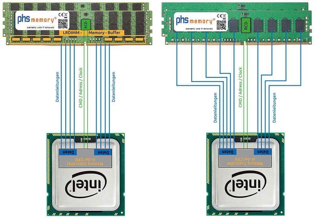
LRDIMM
Load-Reduced DIMM take buffering a step further. They buffer both control signals and data, which allows them to support much higher memory capacities.
In a way, LRDIMMs “trick” the CPU into thinking there are fewer memory chips than there actually are. The trade-off is a slightly higher latency compared to RDIMMs.
If you inspect them physically, you’ll notice that LRDIMMs have additional buffer chips in front of the memory chips, on top of the register.
UDIMM
With Unbuffered DIMM, there’s no buffering at all. The memory controller talks directly to the memory chips. They offer lower latency, but also support lower capacities, which is why they’re more common in desktops than in servers.
Memory Ranks
A rank is a group of memory chips that the CPU sees as a single block of memory and accesses at the same time.
One analogy I found on the internet and really liked is: think of a DIMM as an apartment building, and each floor as a rank. More floors mean more capacity but the memory controller can only access one floor at a time. More ranks mean more electrical load.
You’ll often see memory labeled like:
- 1Rx8 – Single rank
- 2Rx8 – Dual rank
- 4Rx4 – Quad rank
The x4 and x8 part refers to the chip width whether each chip handles 4-bit or 8-bit data.
Memory Speed
Memory speed is measured in MT/s (Mega Transfers per second). DDR stands for Double Data Rate, which means data is transferred twice per clock cycle. You’ll see memory labeled like this:
- PC4-2133P → 2133 MT/s
- PC4-2400T → 2400 MT/s
- PC4-2666V → 2666 MT/s
One important thing to remember: installing many high-rank DIMMs can cause the system to drop the memory speed automatically.
Memory Channels
A memory channel is a dedicated data path between the CPU and the memory. Another great analogy i found on the internet is like lanes on a highway: one lane limits traffic, but multiple lanes let much more data move at the same time.
Memory channels live inside the CPU, not on the motherboard. Each CPU has its own memory controller, and the number of channels depends on the processor model.
For example, the Intel® Xeon® E5-2620 v3 supports:
- 4 memory channels
- Up to 3 DIMMs per channel
- That’s 12 DIMMs per CPU
So in a dual-socket Dell PowerEdge R730 with two of these CPUs, you’ll see 24 DIMM slots 12 per CPU. CPU1:
CH0: A1 A5 A9
CH1: A2 A6 A10
CH2: A3 A7 A11
CH3: A4 A8 A12
CPU2:
CH0: B1 B5 B9
CH1: B2 B6 B10
CH2: B3 B7 B11
CH3: B4 B8 B12
Notes on Populating Memory
- Instead of filling all DIMMs on just one channel, it’s much better to spread memory evenly across all channels.
- Bad memory population layout
Channel 0: 3 DIMM
Channel 1: 1 DIMM
Channel 2: 0 DIMM
Channel 3: 0 DIMM
- Recommended population layout
Channel 0: 1 DIMM
Channel 1: 1 DIMM
Channel 2: 1 DIMM
Channel 3: 1 DIMM
- One should not mix RDIMM and LRDIMM in the same system
- x4 and x8 DRAM based memory modules can be mixed
- Up to three dual- or single-rank RDIMMs can be populated per channel.
- Up to three LRDIMMs can be populated per channel regardless of rank count.
- Mixing of more than two memory module capacities in a system is not supported.
- Populate four memory modules per processor (one DIMM per channel) at a time to maximize performance.
- Populate all the sockets with white release tabs first, followed by the black release tabs, and then the green release tabs.
- In a dual-processor configuration, the memory configuration for each processor should be identical. For example, if you populate socket A1 for processor 1, then populate socket B1 for processor 2, and so on.
- If memory modules with different speeds are installed, they will operate at the speed of the slowest installed memory module(s) or slower depending on system DIMM configuration.
- When mixing memory modules with different capacities, populate the sockets with memory modules with highest capacity first. For example, if you want to mix 4 GB and 8 GB memory modules, populate 8 GB memory modules in the sockets with white release tabs and 4 GB memory modules in the sockets with black release tabs.
- 2666 + 2400 + 2133 → system runs at 2133 MT/s